This post is part of a series about Prism, an open charging station
The basic building blocks of an EVSE are pretty standard.
We start, of course, with a power supply for the low voltage circuitry. While this may seem a very simple and straightforward piece to solve, there are a lot of variables to consider: we need ±12V at 12mA for the pilot signal, 5V and 3.3V for the logic, and an isolated 3.3V for the high voltage measurement circuit, with signal isolation too. We will think about this after testing the other components to have a clearer idea of all the requirements.
Then we have a microcontroller driving the PWM signal to the car and measuring its feedback. We can then drive a contactor or relays to power the car, and that’s the bare minimum to start charging.
Power is transferred through a Type 2 connector (commonly called Mennekes due to the brand that lobbied to make it standard in Europe). This connector has five pins for three-phase up to 63A, although almost no one goes over 32A, and two signal pins for Proximity detection and Control Pilot.

Trivia: as I wrote earlier, Tesla uses the Pilot pin for single-wire CAN, but that’s not the only non-standard way Tesla “hacked” this connector. They are also the only cars to use it for high speed DC charging, by supplying up to 500VDC using N and L3 for the positive terminal and L1 and L2 for the negative. This particular mode is initiated via CAN through a cryptographic exchange, to make sure no other car explodes by trying to charge at this non-standard station.
The PWM circuit
J1772 is a very old standard; unfortunately, while the industry could have gone with some nice bidirectional communication protocol like CAN, due to legacy compatibility we’re stuck with this crappy PWM signalling method (there’s a proposed Power Line Communication standard but no car implements it yet, and IMHO it adds unnecessary costs – I can add it later). How does it work?
It’s very simple. Here’s what happens:

- The EVSE outputs a +12V DC signal on the Pilot pin
- Inside a car there’s a diode D1 and a resistor R2 creating a voltage divider with R1, that brings the Pilot voltage down to about 9V
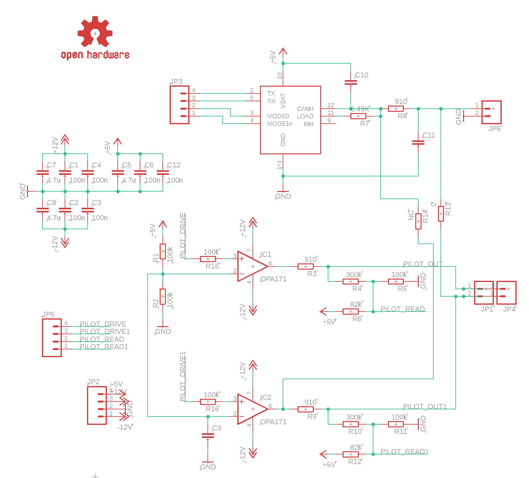
- the EVSE measures the Pilot through R4, R5 and R6. These resistors translate the ±12V output to 0~3.3V signals for the microcontroller ADC. As soon as it reads 9V, the microcontroller starts generating a 1kHz PWM signal on the PILOT pin (via the CONTROL output).
- This PWM signal tells the car how much current she can draw. This can be a number from 6A to 80A. In the range from 6A to 51A, the value is calculated as DutyCycle = Ampere * 0.6
- The car perpares to charge; when she’s ready, she closes the switch to parallel R3 to R2, bringing the high-side of the PWM signal to about +6V (the lower side still goes to -12V due to D1)
- The EVSE can now close the contactor and supply power to the car.
- If the car wants to stop charging, she just disconnects R3 and the EVSE will immediately disconnect the contactor.
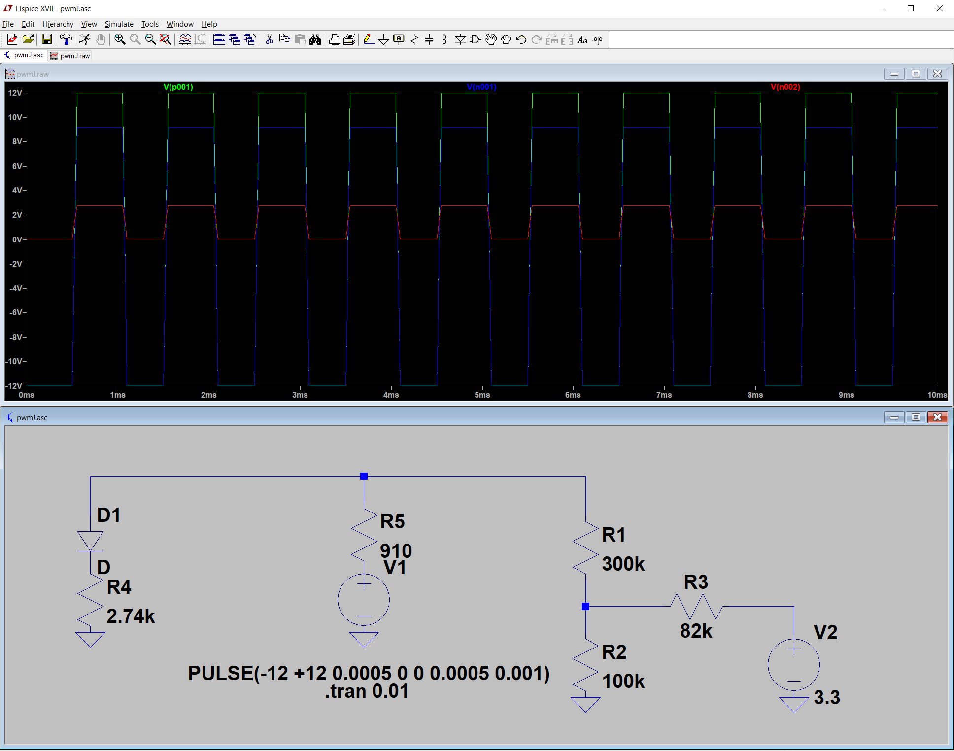
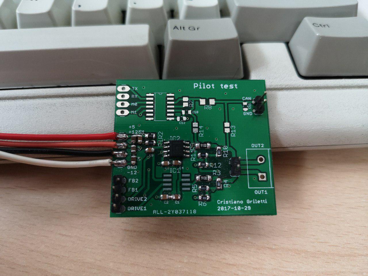
After calculating the resistors and simulating everything with LTspice, I designed a PCB to test various components. You can also find the NCV7356 test circuit in here if you want to test Tesla’s one-wire CAN.
At the time, PCB makers were making great offers for 5x5cm PCBs so I split my test boards into smaller parts. This makes the design modular, and makes it easier to test single circuit blocks. Find schematics and PCB here!
The power board
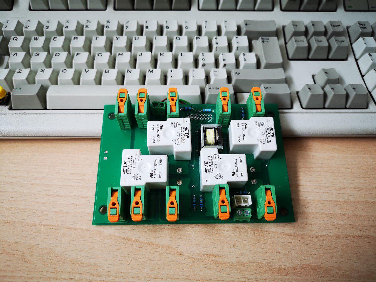
This board was built to test relays and current sensors. I designed it with generous tracks, mirrored on top and bottom, and ordered them with 2oz copper layers; I calculated a +10°C worst-case temperature rise with this configuration, and on my tests I measured a maximum of +4°C at full load, probably due to some air flow around my bench.
Relays are TE T9SV1K15 rated at 35A. There are pads for two types of current transformers: the CSE187L, rated at 30A, and the Pulse PB0027NL, rated at 35A. Both worked well; I prefer the Pulse transformer for its rating and smaller size, in SMD form.
Here I also added voltage dividers to measure input voltage, and to check presence of the output voltage to detect a stuck relay.
I designed a three-phase board and a single-phase one, but never tested the single-phase version. You can find both with schematics here.
Those two circuits controlled by a microcontroller would be enough to trick a car into charging. But that’s just the basics. As we said earlier, we need to do much more to provide a safe environment for our users and comply with standards.