This post is part of a series about Prism, an open charging station
Supplying power to everything is not as easy as it may seem. We need several voltages to power all the components, here’s the budget:
- Isolated from mains, negative connected to mains earth
- ±12V at 14mA per pilot port (0.33W)
- 5V at max. 360mA for the user interface RGB LED strip + up to 40mA per port for contactor relays (0.6W to 2.2W)
- 3.3V at max 14mA for the STM32F103 (0.04W)
- 3.3V at 200mA (with 800mA short peaks) for the Linux module (0.66W – 2.6W peak)
- Referenced to mains neutral
- 3.3V at 23mA for the ATM90E36 (0.07W)
From AC to DC
So we need a total of about 1.8W in normal operation, up to about 5W peak in the worst case.
At first I started to look at triple output supplies with ±12V and 5V outputs. Unfortunately, looking around I couldn’t find any triple output module in a reasonable size (and price); it was time for plan B.
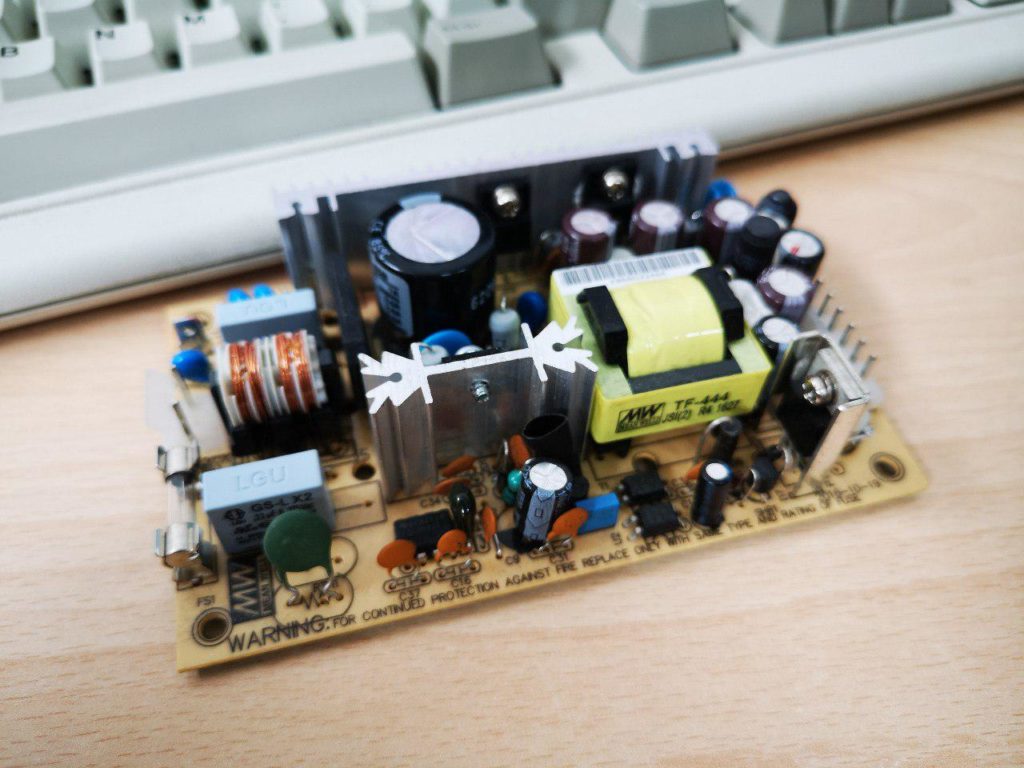
The next best thing would have been to have a single 12V or 5V supply and convert that to all the voltages I needed. Since the biggest load is on the 5V line while the 12V one only requires 14mA, it made more sense to get the 5V output module. Initially the idea was to add way more LEDs, so I started testing with the MeanWell IRM-20-5. This 20W AC supply module outputs 5V at up to 4A.

±12V Pilot signal supply
Now, how can we generate a ±12V supply from 5V? Looking around for schematics I didn’t find much; most of the circuits are designed for very low current RS232 communication (there are plenty of ICs for that like the venerable MAX232). I could generate +12V with a simple boost converter, and then invert that; however, the only inverter ICs I could find are rated for 5V. The capacitive inverter TC7660S may work, but it’s too close to its absolute maximum rating and its output impedance is way too high.
The TPS65130 is a switching boost converter with an integrated inverter at up to 800mA, but it’s very expensive and requires a lot of (expensive) components to work. The LTC3261 would be perfect if it didn’t cost 6€ a piece (plus the boost converter).
There’s a nice trick to use a Boost converter to generate both a boosted voltage and its negative; unfortunately switching ICs have a feedback only on the positive line so this wouldn’t work with our unbalanced load. However, since on the Pilot signal the big load is normally only on the positive side, there should be a way to make this work. I have a few ideas that I still haven’t managed to fully explore.
After testing some different solutions, I concluded that the best “compromise” to supply the ±12V rail is to simply drop in a DCDC module like the MeanWell DPU01L-12. They’re cheap, easy to implement and work very well in this application, despite not being regulated.
Isolated 3.3V for the High Voltage measurements
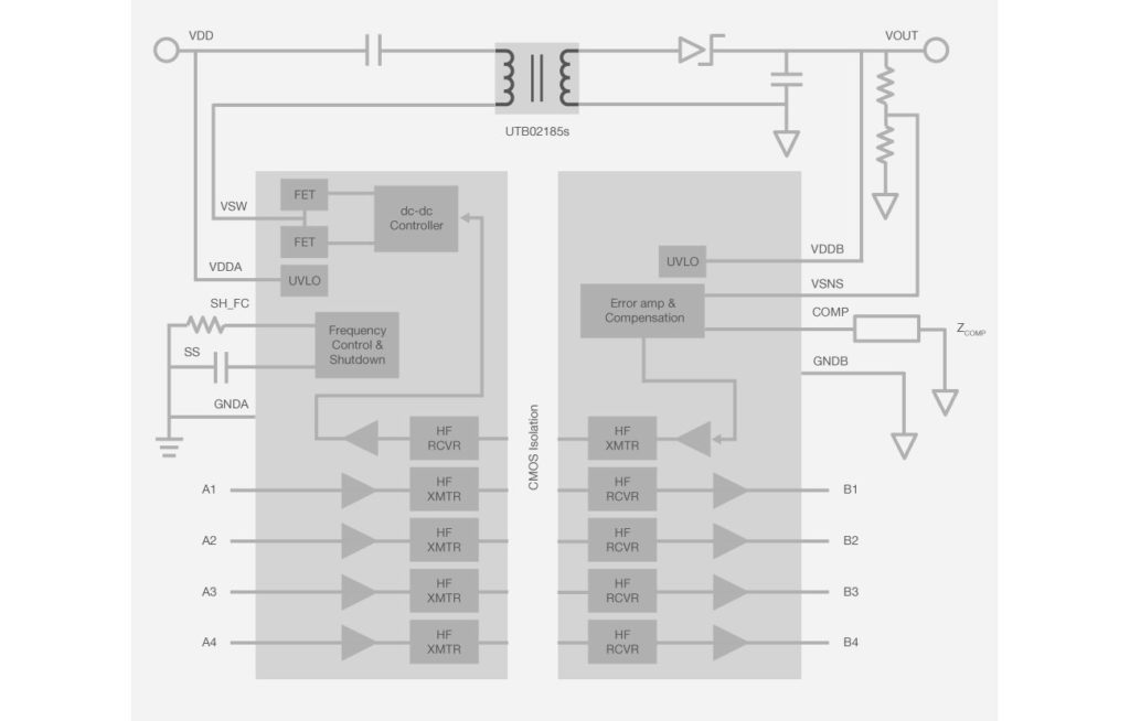
The holy grail here is the SiLabs Si88341 IC. This device integrates an isolated DC/DC power supply and four channel logic isolation in a very nice package. I don’t know what it is that makes me appreciate this IC so much, but I think it’s truly gorgeous. Unfortunately, it’s not cheap at 5€ in single quantities, plus the transformer, plus the effort to make it work as designed.

The next best thing is a combination of the Si8641 digital isolator for the signal, and a standard 5V DC/DC isolated module like the RFM-0505S. From there, a simple 3.3V LDO will regulate the supply for the power meter. Easy, lazy, works!
3.3V supply for the Linux module
Here the requirements are simple: low ripple, about 200mA continuous with 800mA peaks. Normally I’d just paste here my usual supply block that I used in many other projects, based on the MP1584:
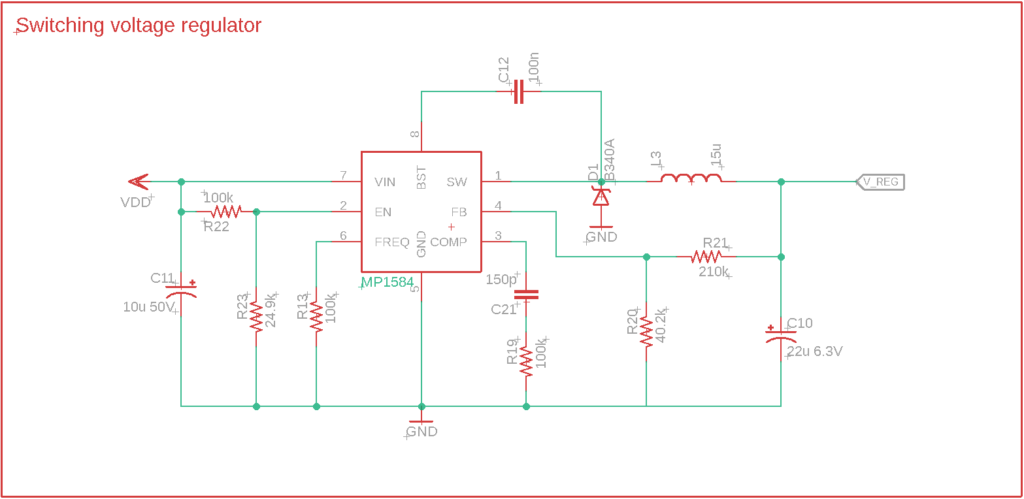
But that design is optimized for a wide input voltage (up to 28V!), while here we have a fixed 5V input and size and efficiency are more important. So I went to one of my favorite online tools, the TI WEBENCH, to find a better part. Here you just have to specify your requirements to get a nice list of options to choose from:
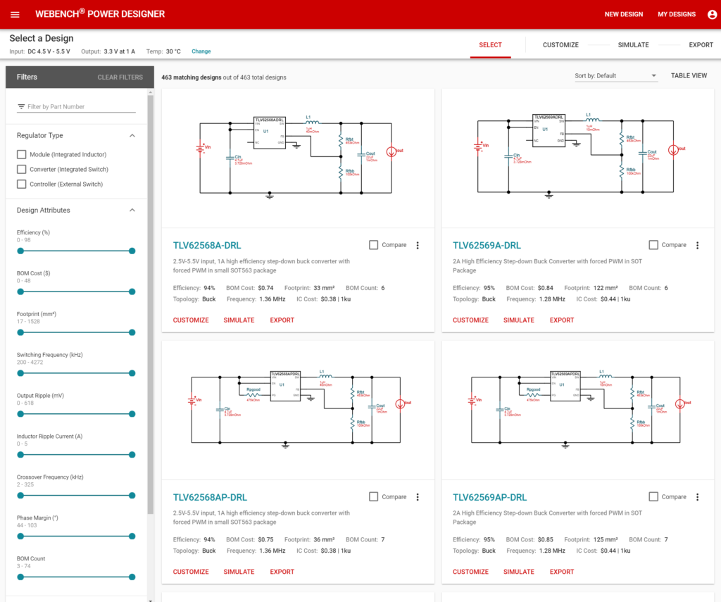
I ended up picking the TLV62568, a nice tiny switching regulator: efficient and cheap. With Webench it’s also very easy to simulate the circuit behavior:
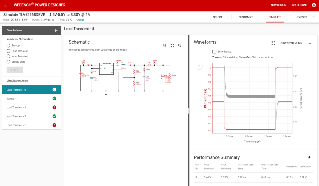
After testing in real life with various components, I increased the filter caps value and rerouted everything a few times to reduce noise and ripple due to the current spikes from the wifi radio, and managed to get the ripple to a reasonable level.
And that’s it! I’m starting to think that I should have written these posts at the same time as events were unfolding, as reading them again doesn’t make it look like it took much effort to get this project going. Maybe if I wrote them during one of the sleepless nights I had, I would have been able to better show the stress and pain I had to go through! :)
Enjoy my updated Eagle library with all these components and more!