 This article is part of a larger project to build a multi-purpose board that can replace a Nokia 3310′s mainboard.
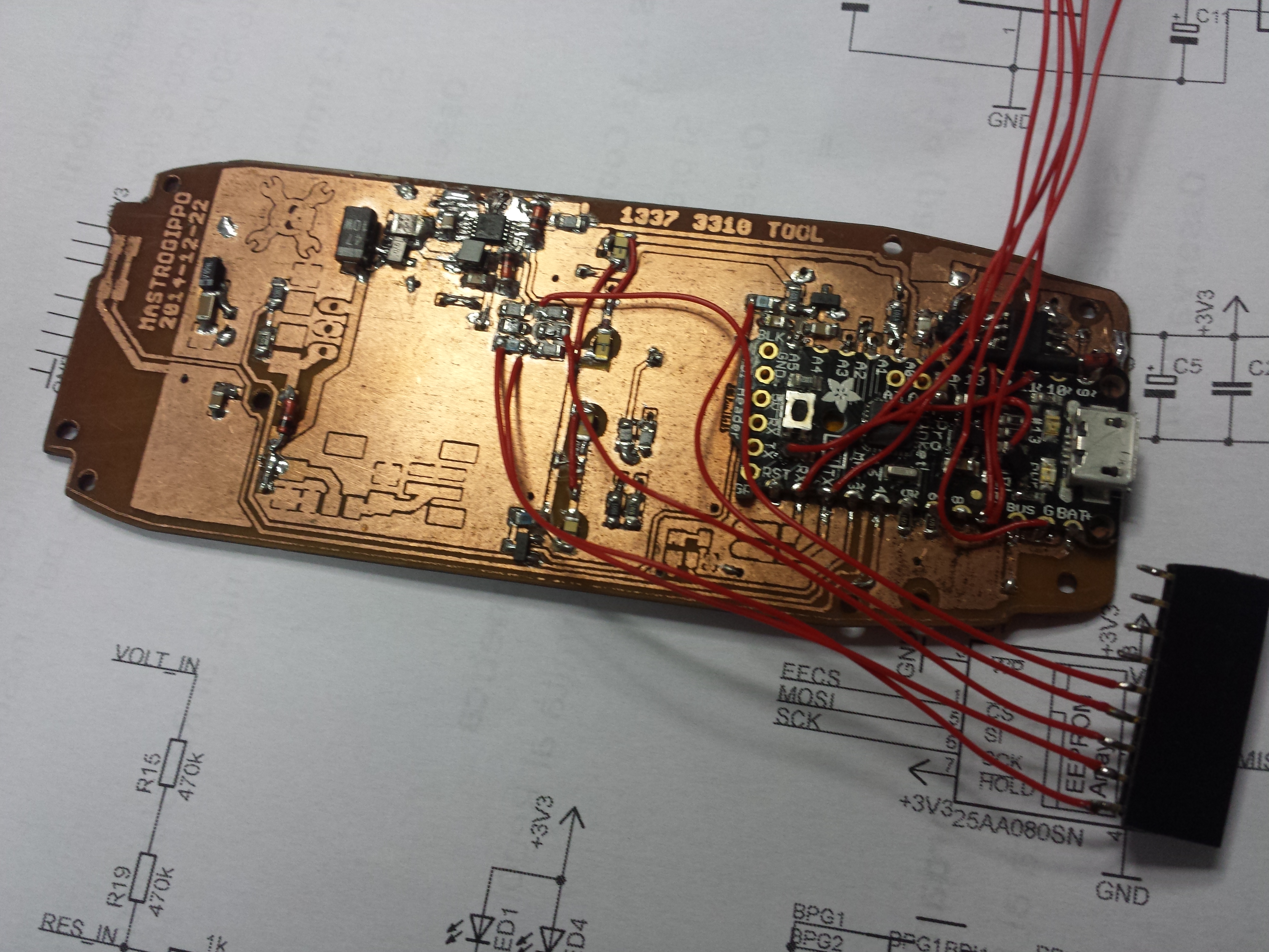
Well, today I started testing the analog input circuitry. As you can see, I’m soldering wires directly from resistors to the connector. The casual observer may see this as being too lazy to route a proper connector on the PCB, but it’s really a very sophisticated way to relieve stress on the connector! :P
I also had to add a bodge flyback diode to the buzzer, as I forgot to include one… That’s the second error on the PCB: the other one is taking for granted that I could put two green LEDs in series. I’m too used to modern, super efficient LEDs, but since I’m reusing the original Nokia 12 years old LEDs, they need a bit more current and seem to have an higher forward voltage than the ones I use everyday.