This post is part of a series about Prism, an open charging station
The EVSE decides what’s the maximum current a car can draw; this is because only the EVSE knows how it’s installed. If it’s a portable EVSE, the Pilot signal will limit the charge to the AC plug or cable rating. If it’s a wallbox, the installer should have configured it according to the mains wiring specifications. The car should comply with that limit, and the EVSE should disconnect the car if it exceeds it, to prevent fires and avoid tripping the circuit breaker.
Since we already need Current Transformers on each line for this, why stop at measuring current? We can, for example, record power and measure the power factor.
When I started thinking about how to do this, I knew the basics and the theory. Experimenting with the OpenEnergyMonitor and the OpenEVSE, however, showed me that this topic is way more complex than it seems.
Luckily I’m lazy, and as Bill Gates says:

So instead of using a microcontroller and complex software like everybody does, I looked around and I indeed found a great and easy(er) way to accomplish this task: the marvelous Atmel/Microchip ATM90E36A. This chip is a three-phase energy meter, it also comes as a single-phase version and a cheaper version with less features. It’s a full-featured metering IC, measuring all parameters like Vrms, Irms, mean active / reactive / apparent power, frequency, power factor, phase angle, Total Harmonic Distortion (THD) and Discrete Fourier Transform (DFT) for the harmonic component. Everything is exposed via SPI, and there are programmable alarms for voltage sag, phase loss, reverse voltage/current phase sequence, reverse flow and more.
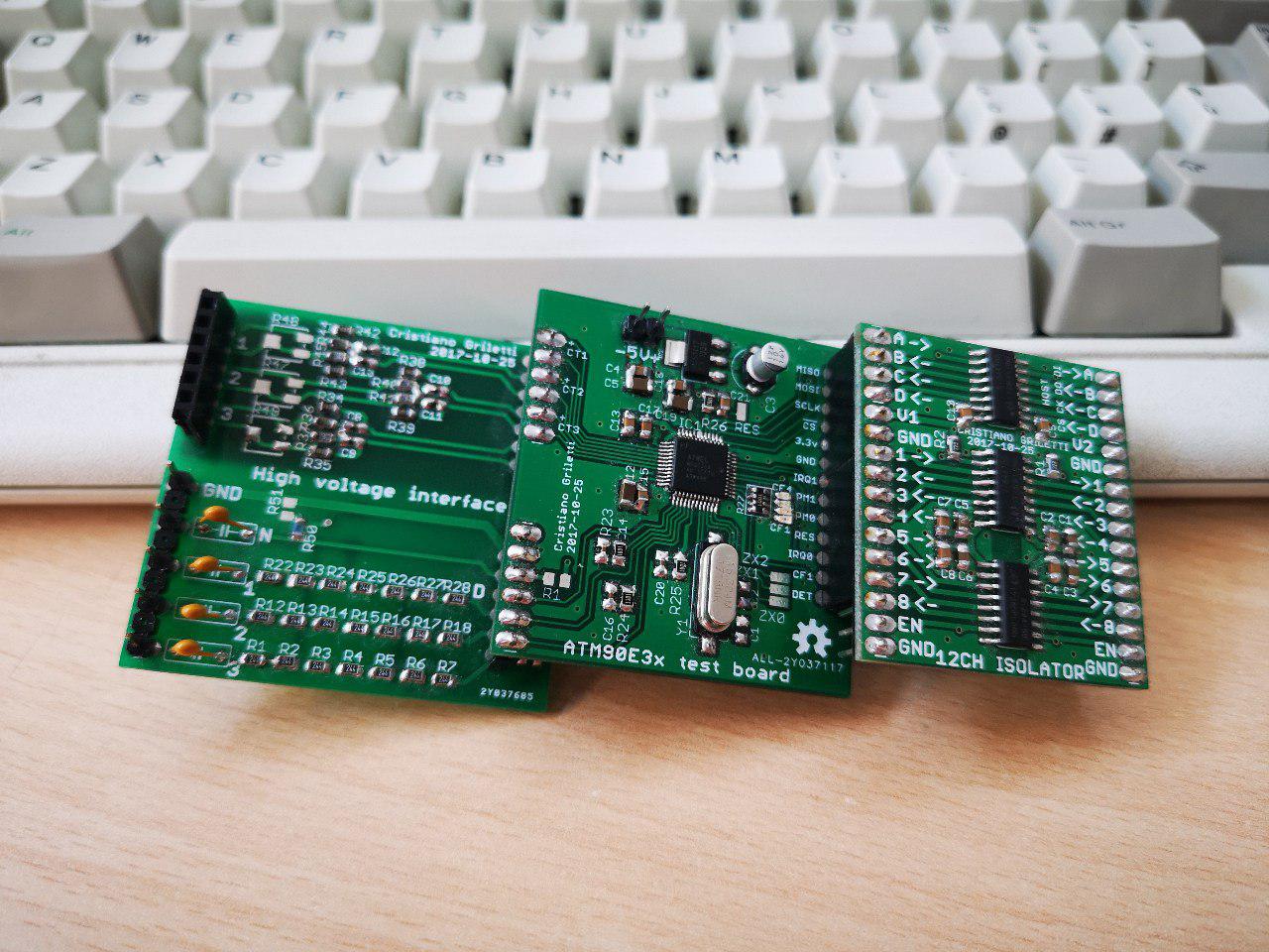
Still following the 5x5cm board module philosophy, I designed three cute boards to experiment with this IC.
 The high voltage input board
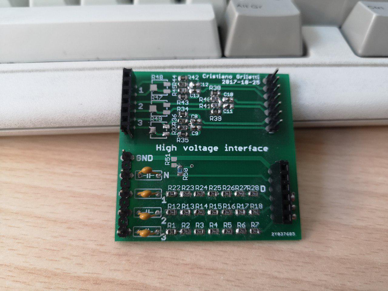
This is simply an interface board with proper conditioning for the current transformer and a voltage divider to measure the AC line voltage. Nothing to see here! Sources here.
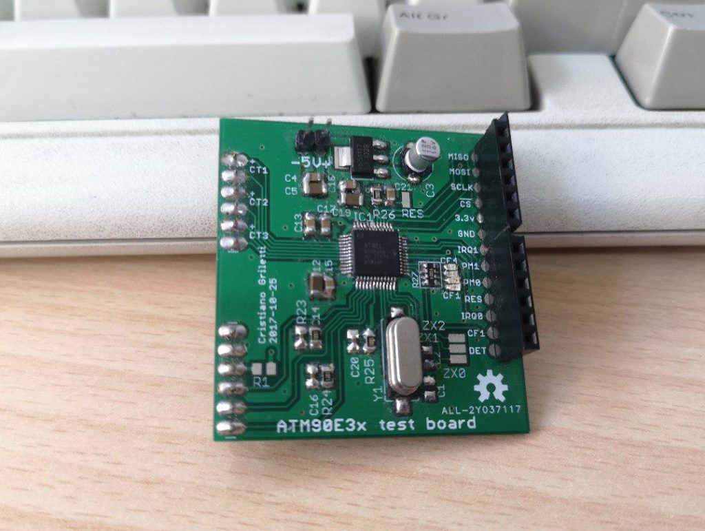 The ATM90E3x breakout board
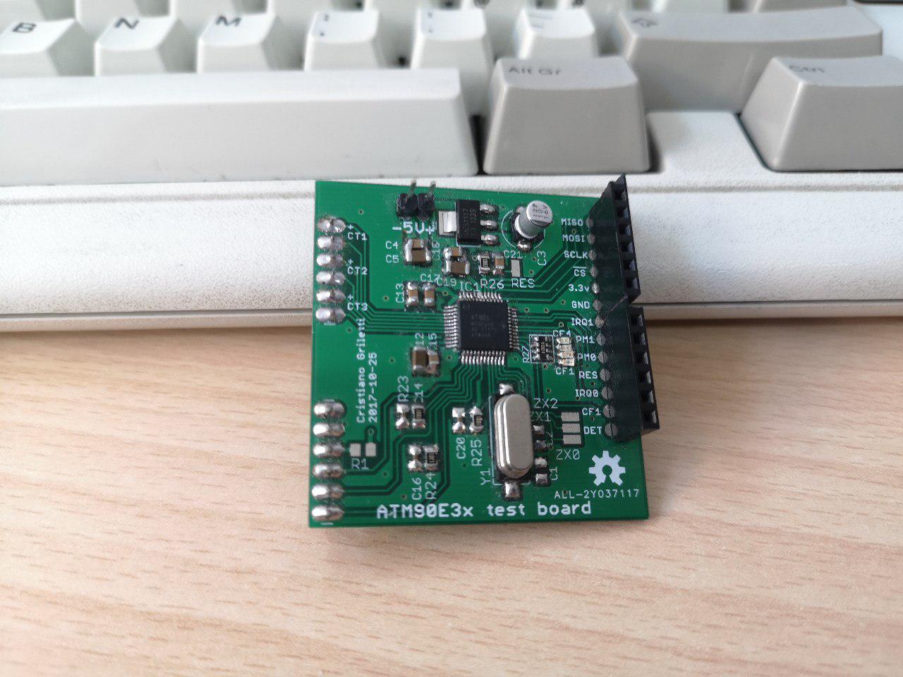
This board collects all the passives needed to run the ATM90 IC. It has to be powered from an isolated 5V supply from the top pins; I just used a USB phone charger for this. There’s space for two capacitors for the crystal; they’re not required as the IC has internal caps, but different crystals may require some adjusting. Sources here.
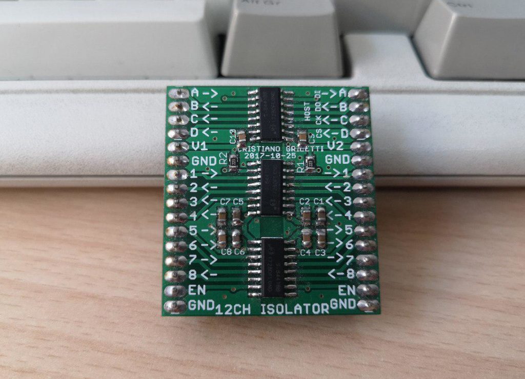 The 12 channel isolator
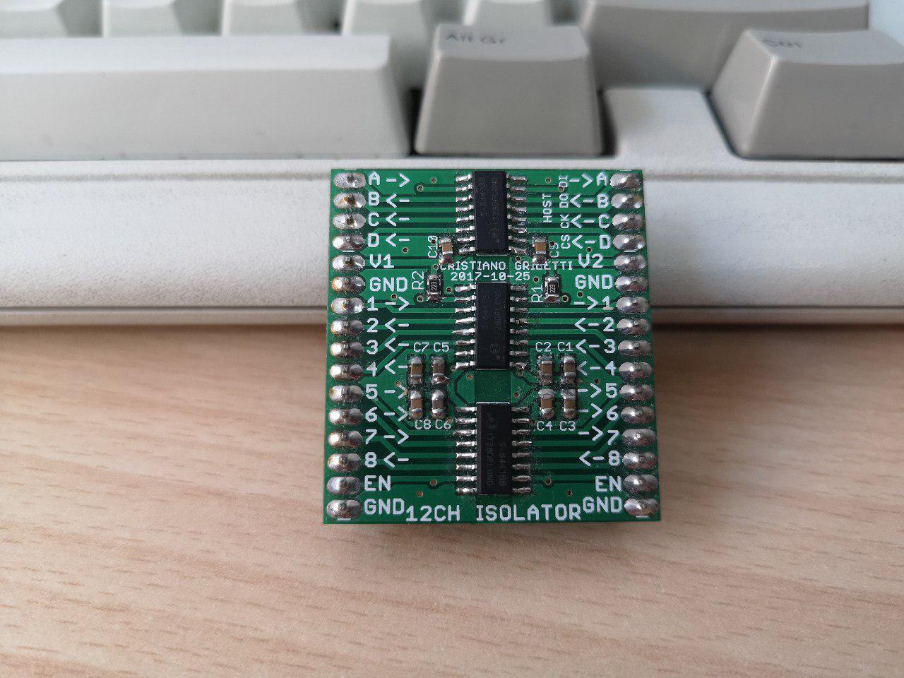
Looking for options to avoid bulky optocouplers, I stumbled across the great Si844x. These chips have four capacitive isolated digital I/O each, and are great for our SPI application. Adding two more ICs brings the total I/O count to 12, so I can read the other outputs from the ATM90 and reset it.
This board will definitely come in handy for a lot of other projects too! And it’s breadboard-friendly! Find sources here.
I’d love to write a long explanation of this three-module circuit, but there’s really not much to say: it’s the lazy route, we just have some signal conditioning, basic passives and an isolator. The software part is a bit more complex though.
Some software
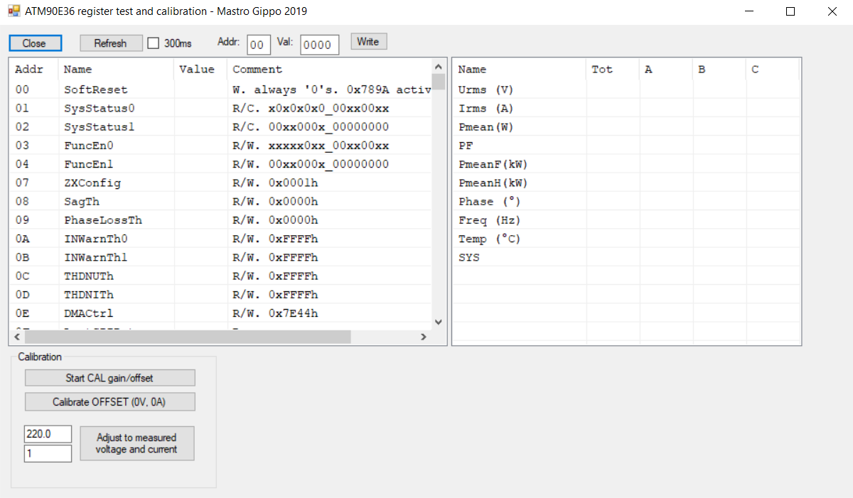
Atmel made a really nice board to test the ATM90E3x chips, the M90E3x-DB. This board is a design reference for a smart meter. I features a microcontroller connected to the ATM90 IC, with some basic software to drive a display and communicate via the serial port. It’s super expensive though, so I requested the sources to Microchip and they kindly provided a copy of all the documentation. That includes a very nice software, ATM90ExxGUI.exe, that helps reading and interpreting all registers, and testing and calibrating the IC:
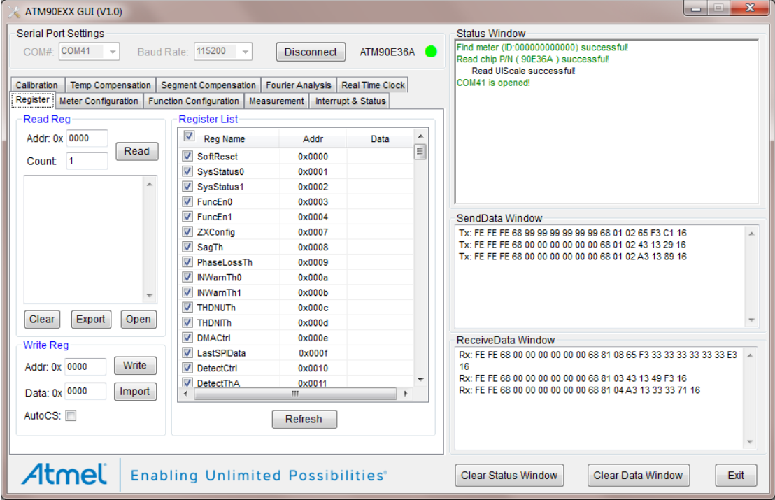 But wait… What’s that protocol?? I spent a lot of time analyzing it; luckily there were a lot of screenshots like this one in the documentation so I could at least start to copy requests and answers to emulate parts of the conversation. Reading further in the documentation, I found out that “The GUI adopts user-defined DL/T645-1997 communication protocol.” This is an ancient protocol especially designed for communication with energy meters. The only useful documentation I could find is this, and it only describes a lower layer so it doesn’t help much with the custom commands for this board. There are sources for the firmware of the demo boards microcontroller, but they’re very messy and badly documented. Luckily the GUI program is written in .NET, so a simple decompiler can convert it back to its source, ready to be debugged, modified and recompiled.
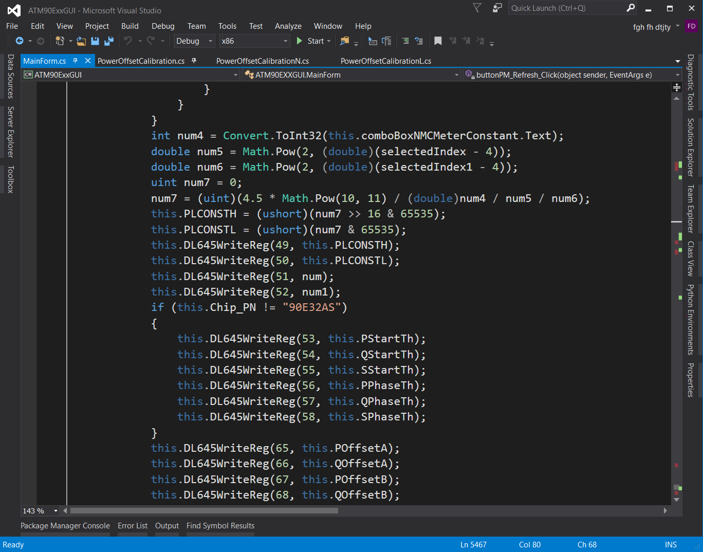
Thank you Atmel for not stripping function names! :)
At this point I pretty much figured out the protocol, so I programmed an STM32F103 to understand it and send the relevant commands to the ATM90 SPI.
You can find the PlatformIO mbed sources for the STM32 here, but Atmel programs are copyrighted so you’ll have to find them yourself.
Calibration
The Atmel software is really nice, but there are a few bugs that make it harder to work with. It’s also closed source; I reversed it and could work on improving it, but then I wouldn’t be able to share it, so I wrote my own version with blackjack and a better serial protocol.
 Now I can get live data from the meter IC and start working on the complex calibration process. At first I started testing with a space heater, then I got serious and built a dummy load with a bunch of 100W resistors screwed on an aluminium profile. With a fixed 150ohm resistance and a perfect power factor, I wrote some code to calculate offset and multipliers and automate calibration. I did these tests a long time ago and I took no pictures, but here’s what it looked like:
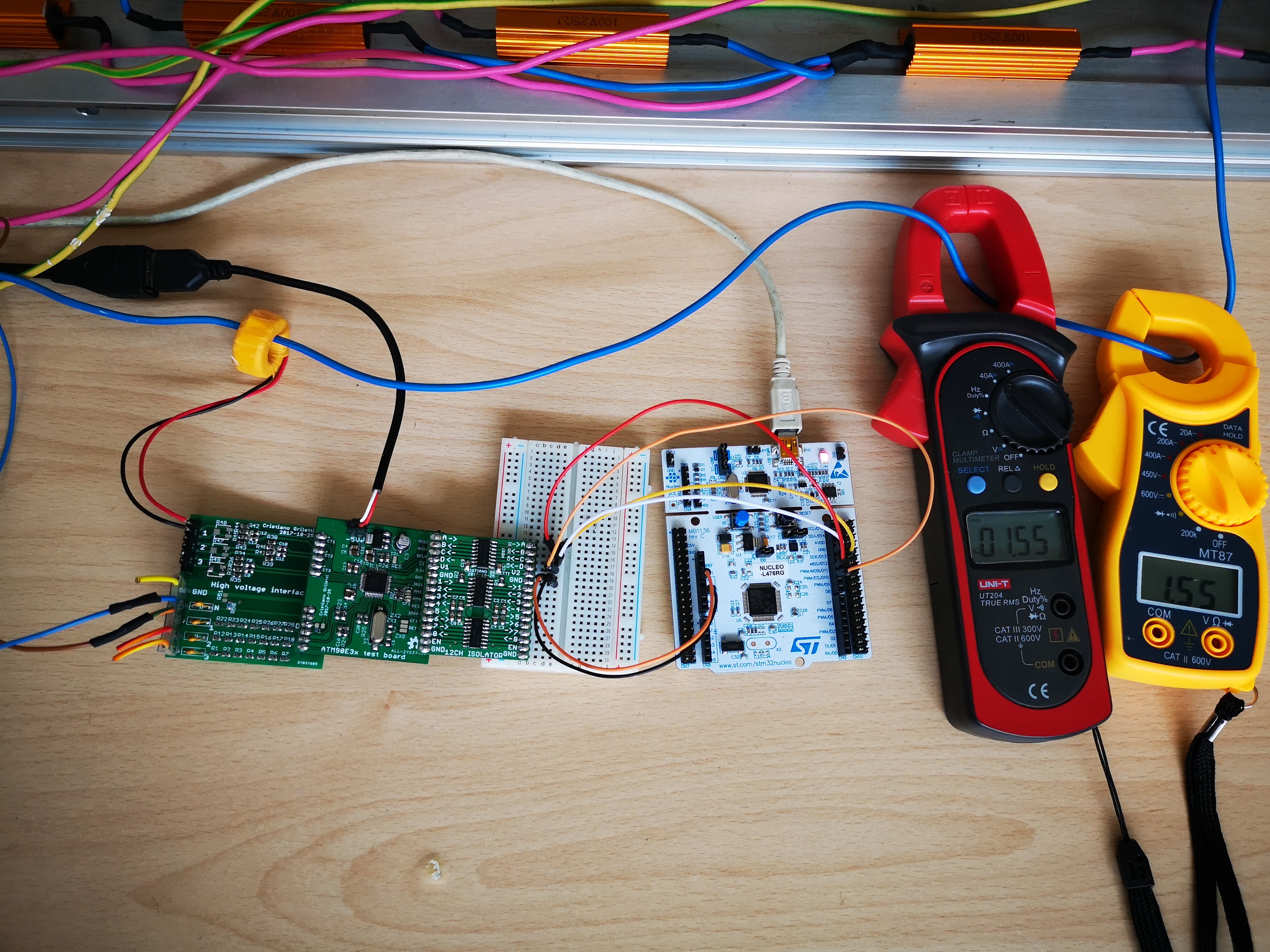
You can download the C# sources here and the STM32 firmware here! Have fun!
I’m loving this series of blog posts. Keep up the good work!
Thanks! You’ll love the next one :)
Great article and great idea to do it the “lazy” way. Looks like it still took quite some work and care to make it happen.
I am making a wind turbine power monitoring system and want to monitor the raw output from the 3 phase alternator attached to the turbine. At low wind speeds voltage and power also low (eg. 5V at 1A) up to about 400W (maybe 60V?) before starting to brake the turbine and shut it down. Would your breakout board and software be a good starting point for me? If so, may I get access to your design (or purchase a board)? The sources links above are not working.
Hi Doug, thanks for letting me know, I just fixed the links! Now you should be able to see the sources. This project should work for you, but it depends on what you do with your 3-phase signal. If you then convert it to DC, I think you’re better off measuring the DC current and voltage directly!
I will be converting to DC but as I am wanting to characterize the turbine output I was thinking I would measure the output before the losses incurred by the diode (which are considerable at low turbine speeds). Perhaps I am trying to solve an unimportant problem … as the power output at low wind speed is too low to be very useful anyway?
I agree with your conclusion. It depends on how much accurately you want to characterize it, doing it with a DC load, diodes and caps may not be the best but it’s definitely the easiest and cheapest way. You can consider a fixed 0.7V voltage drop for the diodes and take that into account (so 1.4V if you use a bridge config).
Ho visto il reference design che atmel propone per l’uso con i ct , ma non ho capito se valori delle resistenze vanno bene per qualsiasi ct. Esempio posso collegarne uno della ccs da 0-330mV 0-50A, piuttosto che il classico sct013 1v-50A senza apportare modifiche allo schema? Trattandosi di ct con il burden integrato l’unica cosa che mi dubbia è se il partitore di tensione non divida eccessivamente.
Probabilmente non andranno bene, come dici bisognerà adattare le resistenze in ingresso!