An important goal that I set for this project is that it must be easily replicated and modified by everyone; that’s why I went for a 2 layer board and and a microcontroller in a LQFP package. To meet regulations I will probably have to switch to a 4 layer board in the production version.
For the first prototype I went for a SIM800L as the GSM module.
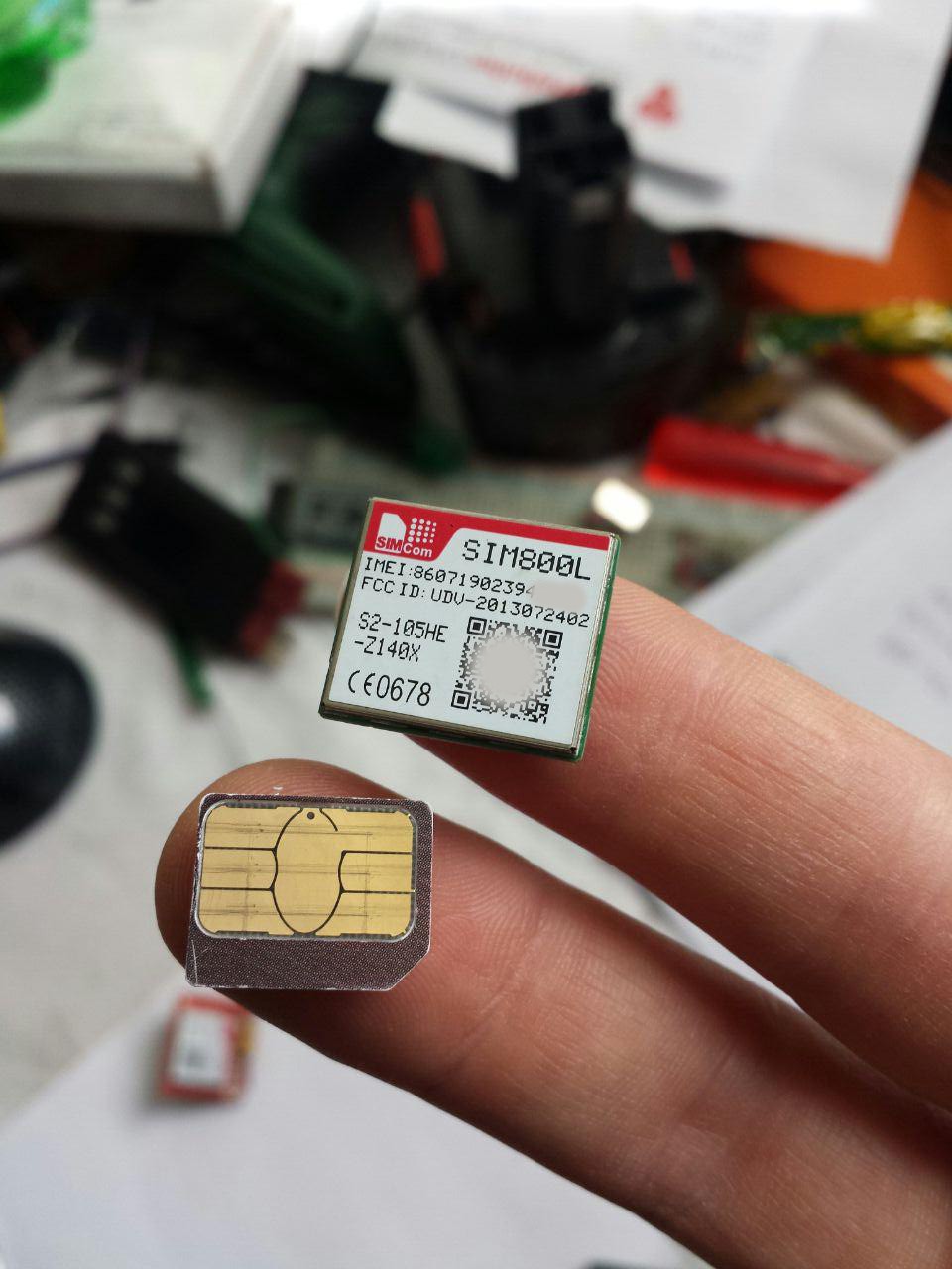
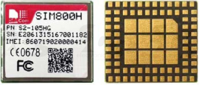
This incredibly small module provides a basic GPRS connection; while the 2G network is getting discontinued in the AT&T nefwork in 2017, there are plenty of other countries where the device will still keep working and hopefully I’ll be able to find 3G/4G devices of a similar size on the market. Another problem of this modem is that it has pins on the bottom like a BGA, and soldering will be harder than a normal BGA chip because there are actually components inside that module that may move around during soldering. Because of that, an important restriction is that this module can’t be oven reflowed while being mounted on the bottom side of the PCB as the components inside may just fall off. And since I’m using two modules here, I need to place them on the same side of the PCB. While I was aware of that problem, I decided not to care as I was going to manually solder them and I knew I was going to redesign the PCB sooner or later anyway.
Unfortunately this came back to bite me: while being extra delicate soldering the GSM module, a SIM card pin didn’t reflow properly so everything worked perfectly but the internet connection. As the Rad1o badge developers, since the missing connection was on a pin on the edge of the board, I tried to fix this by drilling a hole through the PCB and soldering a thin wire to the missing connections
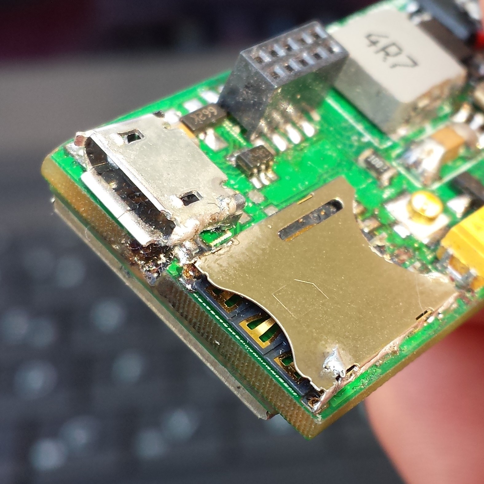 That didn’t work of course, and I messed it up beyond repair, a very nice excuse to start working on the second prototype.
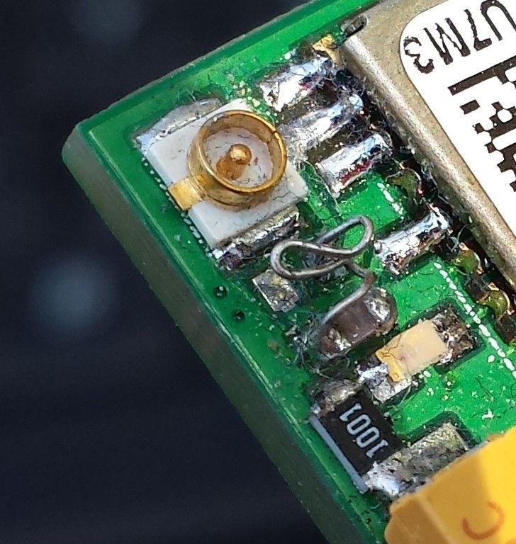
Looking for horror pictures? There you go, here I didn’t have a 1uH inductor to couple the GPS antenna supply and I fixed it with a wiggly wire:
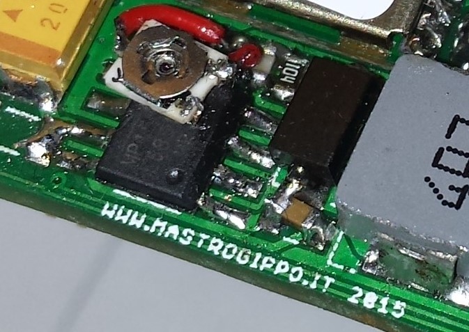
And here I didn’t have the right resistor for the switching regulator, so I used a potentiometer to experiment with different voltages too: