The first prototype of this board was a disaster. I whipped it up in a rush just to fill some spare space before sending the main board to print, and while the Crunchtrack prototype came out nearly perfect, I messed up almost everything in this very simple board.
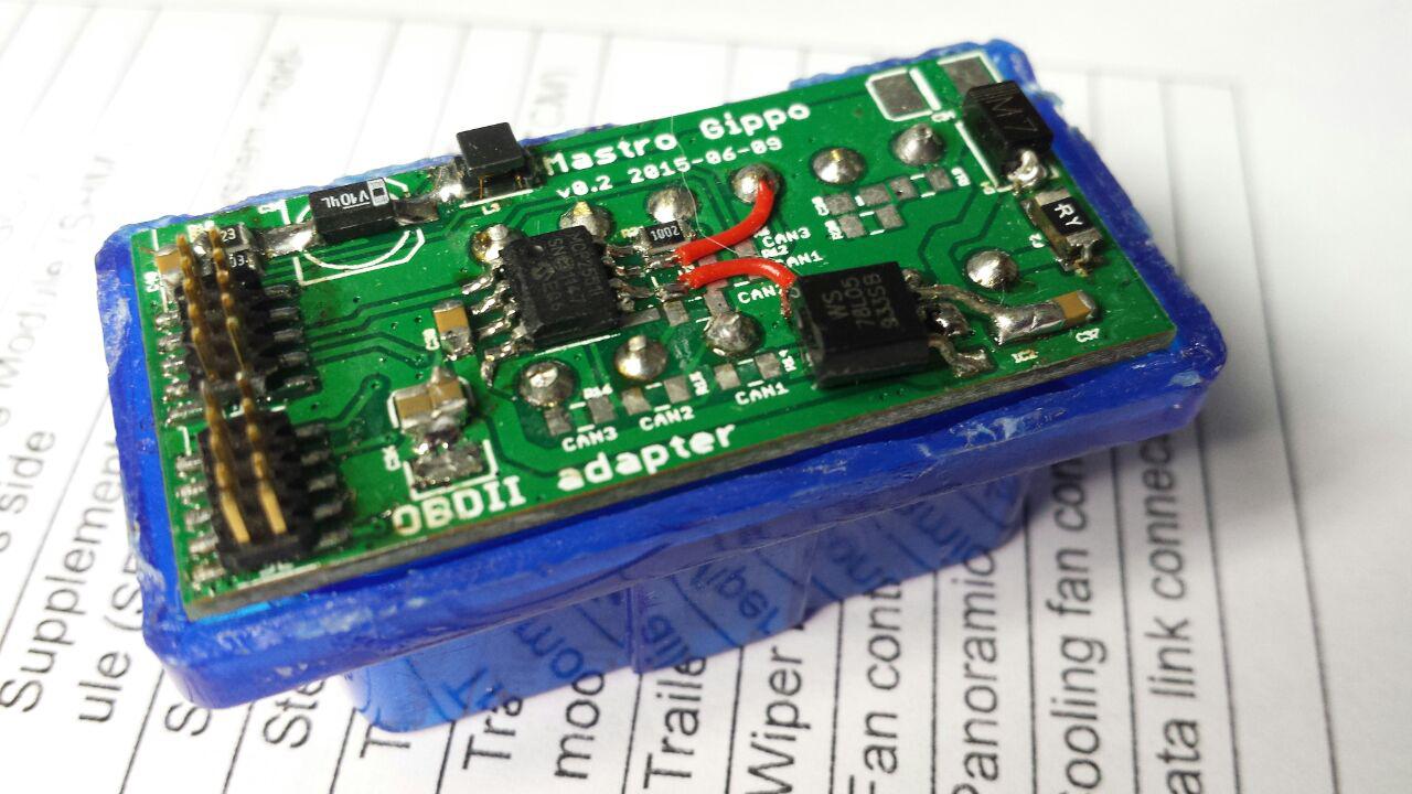
The goal of this board was to provide some supply filter and the CAN transceiver; I also included 6 jumpers to allow the user to choose one of the three standard CAN pin sets. Well, I got them all wrong. I even swapped CAN H and CAN L in two places! So that’s the two red bodge wires. The other ugly thing is the TO92 78L05 soldered on a SOT23 space: I designed the board to accommodate a smaller regulator, but when I assembled it it blew up when I applied the 12V power. Turns out that you can’t find wide input linear regulators in that size, and the one I was using had a max input of 6V.
Last mistake is the big electrolytic cap on the upper left; of course metal can electrolytics are too tall to be squeezed between the two boards and I’ve replaced it with a tantalum one.
So I just redesigned the board, available in the Git, but beware: it’s not tested yet!