This post is written by my friend (and now colleague/intern :) ) [Michele], who worked on the test board. I assigned him this task as it’s the best way to learn about the boards and get up to speed with the project. It also seemed a great way to test the really interesting Exclave project from [bunnie], but -spoiler alert- we’ll have to wait for that.
After manufacturing the boards, we need to test them to make sure that the assembly house built them correctly. This is my first time designing a nail bed, however the task seems quite simple. I have to test the following:
- Short circuits
- Voltage levels from the various power supplies
- Current consumption
- Communication (RS485, I2C, SPI …)
- Other signals to and from the board
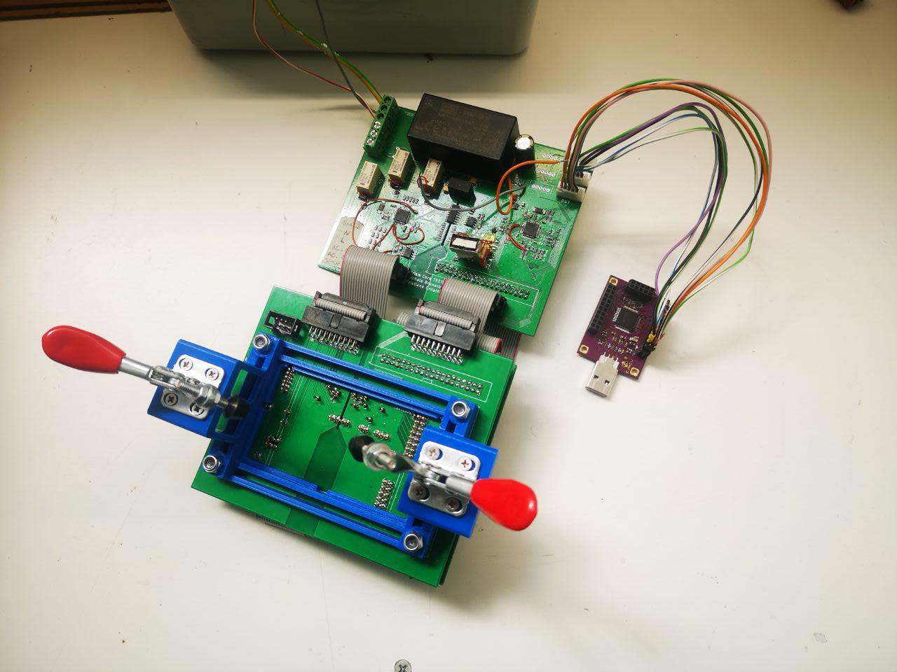
Being this my first time, Mastro Gippo explained me very well what he has in mind for this testing device. It will consist of two pieces: one double-stacked board with pogo pins and clamps to secure the device under test (DUT for short) and another board with all the logic and the supply to do the testing. The logic board will be divided in two parts, one for testing the high voltage side of the DUT, which is attached to the mains power, and another part for the low voltage side (12V max). All looked very clear to me, so let’s get started!
First thing first, the board design.
Using the DUT board file as template all I have to do is putting some holes under the test points and under the holes for the connectors and the pogo pins will be perfectly aligned. Some pads were put at weird angle to avoid overlaps, but this is not a problem.
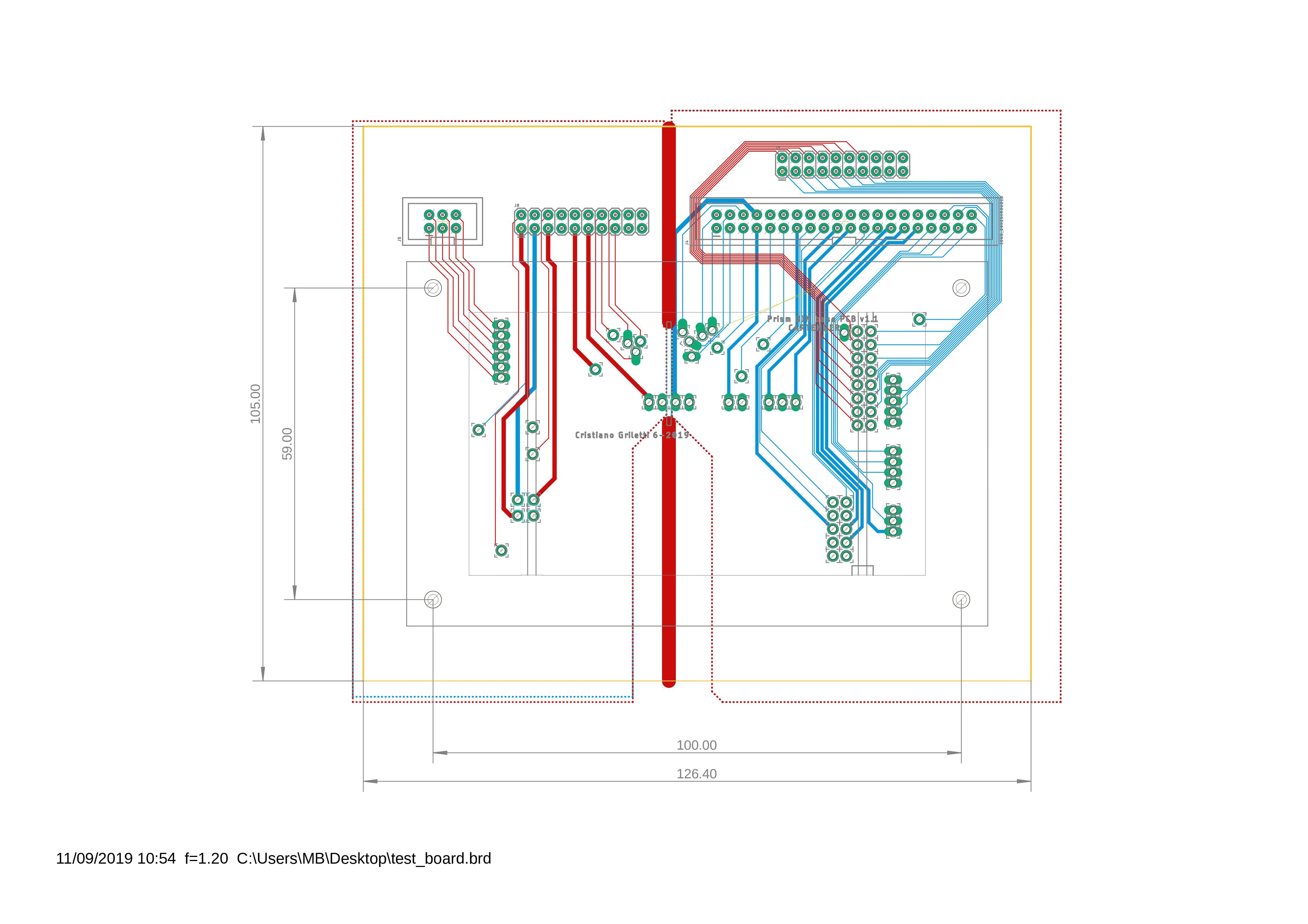
Add some border, put some holes to secure the clamps that will hold the DUT, add connectors, route all signals and it’s done.
Now get on with the next piece of the puzzle, the board with all the power supplies and the logic.
MCUs
The brain(s) of the testing equipment are two STM32F103C8. This was an easy choice, the chip has all it’s needed and is used also in the DUT, so we have a lot of them at hand.
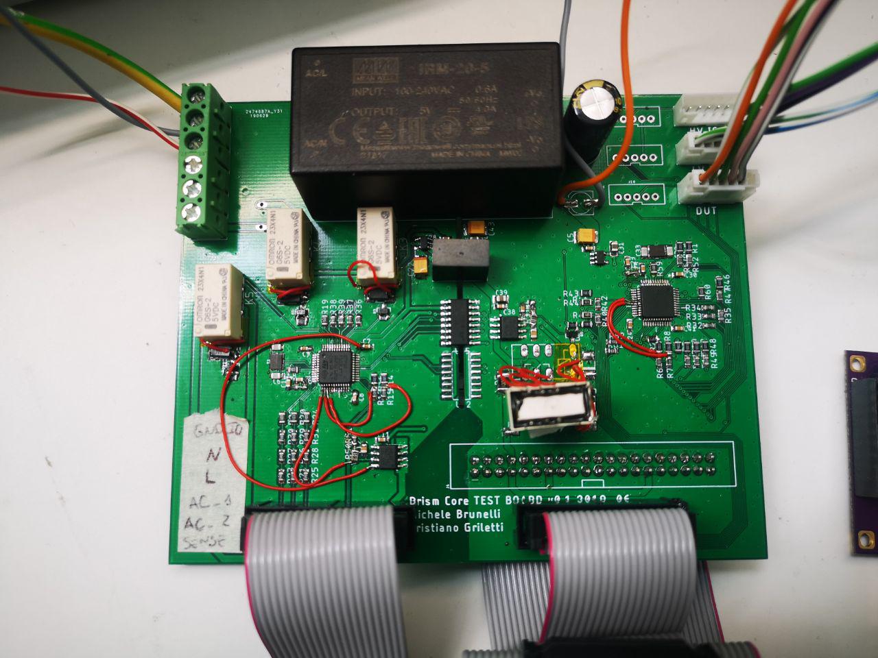
Power supplies
Another simple task. I used the same components and schematic we used for the DUT:
- IRM-20-5 – from 220V AC to 5V DC
- B0505S-1WR2 – isolated DC/DC to take the 5V from the low-voltage side to the high-voltage side
- 2x AP2112K – 3.3V for the two MCU, one for the high-voltage side and one for the low-voltage side
So far so good.
Voltage lines testing
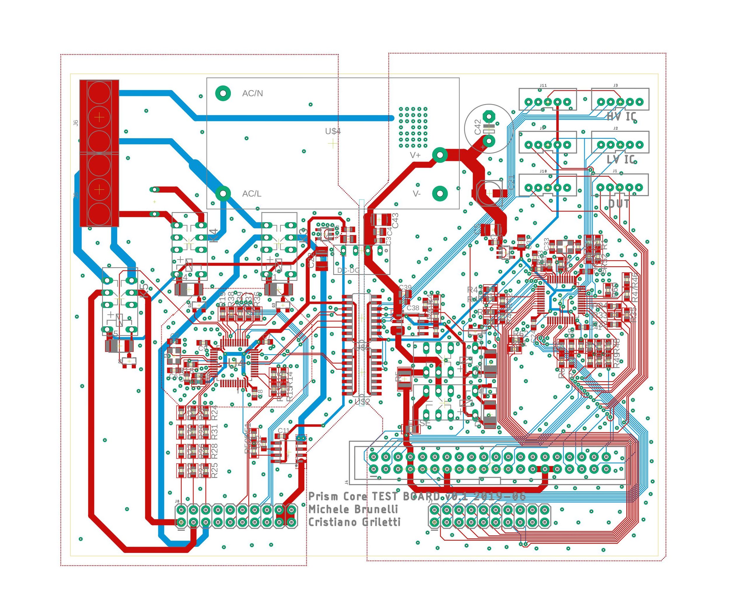
To test the voltage lines all it’s needed are a couple of voltage dividers to decrease the various voltages to under 3.3V, connect the signals to any analog pins and this is it.
Short-circuit and current measuring
I used some relays to switch the 5V and 220V lines that goes from the testing board to the DUT to power it up and two ACS71205B hall-effect current sensors.
First the short-circuit test is done powering the DUT from the 5V line with a 100ohm series resistor to limit the current and check for short circuits. After making sure we’re good, the current consumption is measured first with 5V and then with 220V powering the DUT to see if it’s within the normal range.
Isolation
The central part of the board provide the isolation between the two sides, the high voltage and the low voltage ones. As you can see under the main components of this part, the DC/DC isolated converter and the two SI8441 digital isolators, a slot in the pcb is needed to provide the right isolation. On the top and bottom part some space is left among the two ground planes for the same reason.
Other signals
All the remaining signals to test are routed directly to the two MCUs. For the low voltage side this required a lot of time to route all of them and this took me to mistake a couple of signals. Routing an analog signal to a digital-only pin is not a smart idea…

Unfortunately I noticed that only after soldering all the components and testing.
Boards assembling
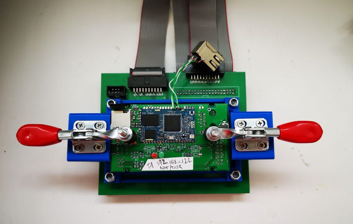
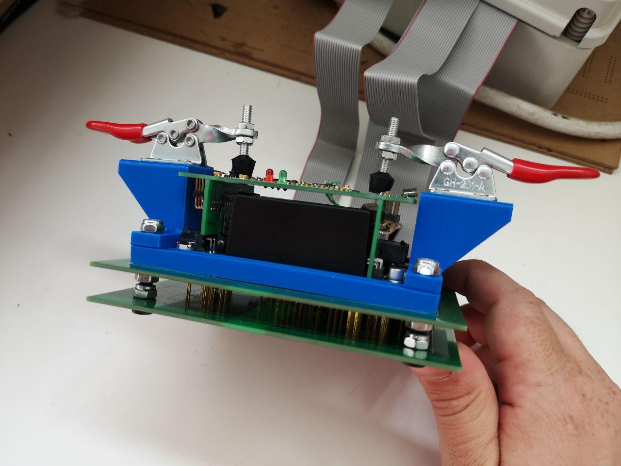
Soldering the pogo pins was a long and tedious, yet quite simple job. I’ve aligned the two boards like a sandwich, soldered 4 pogo pins at the right height and then use my professional pogo pins alignment tool as a base for soldering the other pins at the same height. After this set up, is only a matter on time and patience.
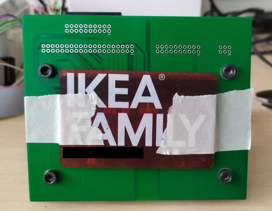
A small tip for you: if you designed the board for vertical connectors but have ordered only 90 degrees ones, the next photo will give you a painless solution.
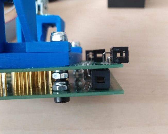
We used locking nuts and bolts to “calibrate” the distance between the two boards and to give robustness to the assembly.
To complete this board the only thing left was the structure for the clamps that hold the DUT in place. Thanks to my experience in 3D modeling and 3D printing I did this right at first try – bravo.

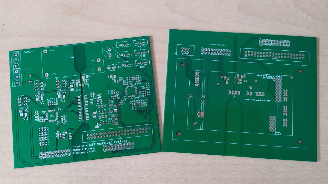
The other board was easier to solder: stencil, solder paste, hot air station, soldering iron and… voilà!
The real testing – a rough journey
With the boards ready it’s time to see if everything’s working.
- Power supplies – OK
- MCUs firmware uploading – OK
- Relays….. uhm, no clicks.
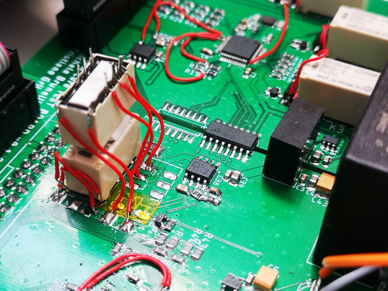
Relays
For some reason the relays weren’t working. I checked all the signals twice, voltage is within range, but they’re completely dead. Maybe I can try to reverse the coil connections…. and now it’s working. Why? Checking the datasheet again, I found the reason for this unexpected behavior. I used the G6S-2 relays, can you spot the difference with the others?
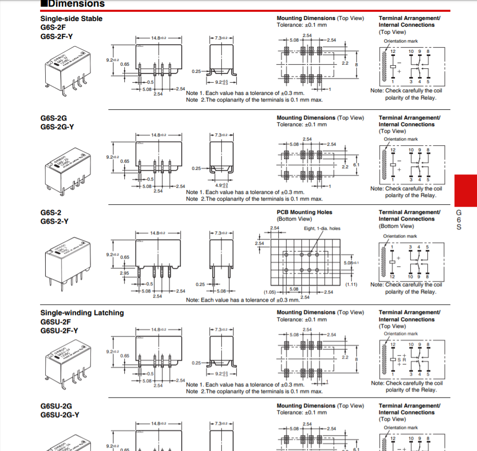
If you’re better than me at this type of game, you probably found what I’ve missed. All the relays have a top view footprint, but the relay that I used was the only one with the terminals represented from bottom view. Of course, that is because it’s the only through hole part, but I didn’t notice that when creating the footprint for the relays. Thank you, Omron. Thank you.

Hopeless, I took my best friend on this journey – the soldering iron – and re-wired all the relays.

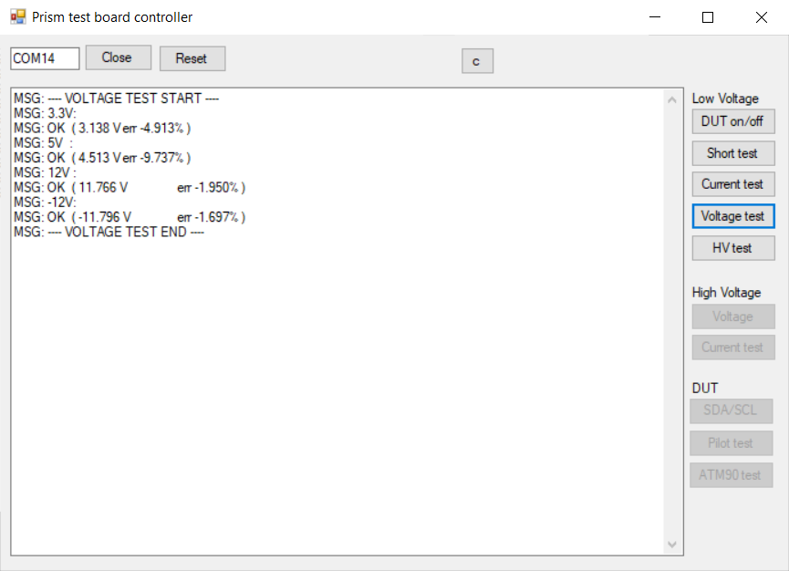
I tested all the relays again and wrote some firmware to check the DUT power lines voltages. Very well, now it’s working. First task completed!
Current sensing
On with the current sensors. All that should be needed is to read a voltage level, do some math and it’s done, right? The short circuit testing worked pretty well, but for some reason the current consumption measurements returned wrong values and were very inconsistent.
Luckily for me, Gippo quickly found the issue: turns out placing an electromagnetic relay near an hall-effect current sensor is not a good idea. So I moved the relay away by flipping it and sticking it on top of the other relay.
That’s it for the low voltage side of the board. I kept going with the high voltage side, at least current consumption need to be measured.
Strip some cables, connect the board to the mains power and check the value read from the current sensor… And it reads wrong values again when the relays closed. But the relays were far from the sensor, what could it be?
It was a problem with the unregulated 5V DC-DC converter supplying the board. The ACS71205B current sensor does not have an internal reference, and having 50 to 200 mV drops on the 5V supply when turning on the relays lead to completely wrong current measurements.
As last hope I’ve tried to supply the current sensor via the regulated 3.3V line, despite the datasheet recommending a supply voltage between 4.5V and 5.5V. After doing some measurements with the sensor powered by 3.3V supply and plotting the values, the results were good but not linear anymore. The only ways left to solve this problem were to add a regulated 5V power supply or connect the 5V line to an analog pin of the STM32 to correct for these changes on the supply voltage. Having exceeded the error count for this board, I will fix this on the next version of the board.
Giving up (..at least for now..)
Being the deadline for the testing device missed, I have to surrender and test the boards manually. At least the pogo pins board give me a handy place to wire everything to the DUT.
But this is not the end. I am a proud person, and soon or later I will win this battle. The next version of the board is almost ready and all the (known) error are fixed.
You can find all the latest sources here!
Stay tuned!
One thought on “Board testing: it’s fun, they said”